| THE INDUSTRIAL RAILWAY RECORD |
© JUNE 1975 |
CORRESPONDENCE
KERR STUARTS FOR SOUTH AFRICA
With reference to this article in RECORD 37 there appear to be no official records concerning the Bezuidenhout Light Railway mentioned on page 82. During the hostilities which took place in South Africa in the years 1899-1902 the British forces laid siege to Pretoria. The Commander-in-Chief of the Imperial Army, Lord Roberts, conceived the plan of building a railway in order that the troops encircling the city could speedily receive supplies at any point on the perimeter. It is said the railway was never constructed and that after the war was over the material was sold to a farmer by the name of Bezuidenhout who farmed in the Pienaarsrivier district. A railway about five miles long was laid and used for the conveyance of lucerne, firewood and various crops: it eventually became known as the Bezuidenhout Light Railway. The Central South African Railways bought this line and after being extended through to Settlers it was named the Pankop Light Railway. Unfortunately the above story cannot be substantiated.
| SOUTH AFRICAN RAILWAYS, JOHANNESBURG |
GENERAL MANAGER'S OFFICE |
(The loco staff in the photographs reproduced on pages 81 and 82 would appear to be Army personnel, so presumably the BLR was at some time a military railway. Possibly the farmer was not called Bezuidenhout? - KPP)
SOME LOCOMOTIVES OF THOS. W. WARD LTD
By mischance some galleys were not corrected before publication of my book, "Locomotives of the L.S.W.R.," and this explains the inconsistencies in the history of 740 (on the last five lines of page 85 in RECORD 49). 740 was in store at Nine Elms Works in July 1912 (744 being at Bournemouth) but it was not purchased by James Brown Ltd (an error for 737). Ashford Works records indicate that 740 was broken up there in May 1924, and are thus at variance with Ward's records. In LSWR days the locomotive's running number was the same as its boiler number, and boiler changes were few on these 2‑2‑0 side tanks. A locomotive used as a stationary boiler at Woolwich Arsenal and returned to Ashford Works in error was recorded as 'small stationary boiler No. WA 740': possibly the locomotive had no number and Ashford Works used the boiler number to identify it.
| TUNBRIDGE WELLS, KENT |
D.L. BRADLEY |
GRIFF COLLIERIES
Since my article on this subject was published in RECORD 47 further information and photographs have come to light. Collieries in the Griff area always had a water problem and it was recorded that more than fifty horses were employed in raising water from the workings. As early as 1713 a Newcomen type pumping engine was installed near Griff Hollows Wharf in a building which is shown on the map on page 3 of RECORD 47 as the "Steam Engine House". Apparently the pump reduced the annual expense of removing water from Ł900 to Ł150. An illustration of the Newcomen pump employed at Griff can be found on page 241 of Volume 1 of Galloway's "Annals of Coal Mining and the Coal Trade" (David & Charles reprints, 1971). According to "Modern Mining Practice", edited by G.M. Bailes, and published by J.H. Bennett & Co, the sinking of Griff "New Colliery" (this would be Clara Pit) was actually commenced as early as 1891, and as such proved to be the first step in the new development of the Warwickshire coalfield. The north (downcast) shaft was 14ft in diameter and the south (upcast) 11ft diameter. Much water was met in the sinking and the type of pump ultimately installed to deal with this problem became universally known as the "Griff" pattern. "Iron," in its issue dated 28th October 1892, confirms the early sinking date for Clara, reporting that sinking had commenced "18 months ago" on the border of General Newdigate's Arbury Estate. Two advertisements for the disposal of locomotives at Griff appeared in "Colliery Guardian" and substantiate information concerning the earlier locomotives. In the issue for 21st September 1900 a 12in tank loco was advertised for sale at Ł400 and it was further stated that it could be seen at work at that time. Later, in the issue dated 19th July 1901, Griff Collieries advertised a 12in cylinder four wheel Black Hawthorn saddle tank locomotive for sale. The latter certainly refers to SWALLOW (Black Hawthorn 174 of 1873) but the former is less specific: it most likely also concerns SWALLOW but could even refer to KNUTSFORD (Sharp Stewart 3471 of 1888), disposal details for which are not known.
| NUNEATON |
M.J. LEE |
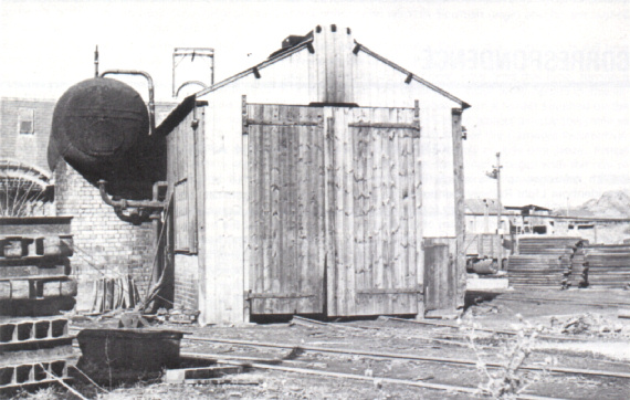
Griff Clara locomotive shed, photographed on 25th October 1952. (K. Cooper)
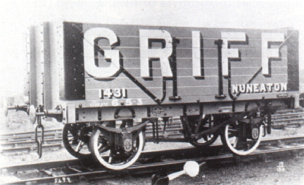
A standard 10‑ton coal wagon in Griff livery built in 1905 by Hurst Nelson & Co Ltd of Motherwell. The basic painting scheme obviously differs from that thought to have been employed latterly, as detailed on page 11 of RECORD 47, though the style of lettering seems to have been retained over the years. (courtesy Historical Model Railway Society)
HYDROLEUM LOCOMOTIVES
Further to this article in RECORD 44 (page 286) and the subsequent correspondence in RECORD 51 (page 155), readers may be interested to learn that a hydroleum locomotive was on display at the second International Colliery Exhibition, held at the Royal Agricultural Hall, Islington, between 25th June and 2nd July 1904. A 2ft gauge railway extending the full length of the Hall was displayed by Arthur Koppel, complete with "a Koppel's hydroleum patent locomotive in full working order, together with wagons of various styles being hauled by this locomotive."
| SHEFFIELD |
"VULCAN" |
FILTER BED RAILWAYS
I am glad that Mr Leleux was able to include a description of transportable filter bed railways in his interesting notes on page 97 of RECORD 50. These were once quite common, but sand filters are now seldom found and may not have been constructed for many years. The Transactions of the Association of Waterworks Engineers for 1898 include a description of how a sand filter works was built for Cardiff Corporation at "The Heath". There were no permanent tracks, but a "large tool shed was also built for storing the plant, etc., on the works; part of this is provided with movable sides and ends, with fire-grate inside, so as to be used as a messroom by the men. Long lengths of Decauville narrow-gauge portable railway are used for removing and replacing sand and gravel in the beds; the trucks etc., when not in use are cleaned and placed in the shed." The works was built by Thos. D. Ridley & Sons, of Cardiff and Middlesbrough. Nearly 23,000 cubic yards of excavation was necessary, so Ridley used a steam navvy. The Rhymney Railway adjoined the site and a siding was put in to enable the surplus to be taken away as fill for a dock embankment under construction at Cardiff. All gravel and sand came from Bideford, Devon, by sailing vessel at 3/- per ton or by steamer at 3/6 per ton delivered into railway wagons at Cardiff Docks. Haulage by rail to the special siding and placing in the filters cost a further 2/- for each of the 6,000 tons of filter medium. The Association of Waterworks Engineers became the Institution of Water Engineers and in their Proceedings I have located descriptions of over twenty railways. Most of these are just a brief reference but sometimes detailed descriptions are given, with locomotive and rolling stock data.
| SOUTHAMPTON |
J.B. HORNE |
ARMY 240
Further information on this locomotive (RECORD 50, page 109) has come to light in documents deposited with Baguley-Drewry Ltd, which suggests that the engine troubles were not entirely due to design or manufacturing shortcomings. A report dated 31st December 1935 stated that after being delivered to Preston (LMSR) on 29th January 1935 the locomotive was out of service for 165 days. Of this total, transmission faults (rubber seals on the air cylinders in the gearbox and loose components in the torque converter) had contributed 40 days and minor engine faults 59 days. There had been no major faults in the engine and the LMSR considered that it was sufficiently reliable, although they felt that the McLaren-Benz and MAN engines would probably prove better in the long term. At this stage of the trials fuel consumption averaged 1.75 gallons per hour (equal to 0.92 miles per gallon) and lubricating oil consumption 13.96mpg, the latter figure being grossly inflated because of frequent changes due to extraneous circumstances.
More revealing is a letter dated 7th January 1939 which relates to a serious engine failure while shunting at Salford. The locomotive was now based at Agecroft and it seems that the fitters there attempted to "improve" certain details of the engine, in particular the decompression gear. Incorrect reassembly of this caused the exhaust valves to lift too far when decompressed and they fouled the pistons. On the day in question the engine ran away and the driver, fearing that it would disintegrate, stopped it quite improperly with the decompressor. Due to the excessive valve lift three cylinders and their associated components were damaged beyond repair. It then became known that the fitters had also been "adjusting" the governor, so the cause of the run-away was no longer a mystery. If something like this could happen four years after the locomotive went into service one is tempted to ask how many of the minor faults reported in 1935 were due to similar interference.
I recently turned up a photograph of Drewry 2047 when new. It carried the number 7400 and was painted grey. This suggests that the decision to number the prototype 150hp shunters in the 7050 series was taken at the last minute - unless, of course, the Drewry locomotive was ordered before the others. An obvious candidate for preservation I would have thought - certainly more so than the "pioneering" efforts of other makers which ignored all the work done on mechanical transmissions by Wilson and Baguley over the preceding fifteen years. It is odd that the Drewry prototype should still be in service more than ten years after a Hunslet contemporary locomotive was withdrawn from regular use - even odder that the "crude" Kerr Stuart 90hp prototype (4421 of 1929) should still be in service too.
| KENILWORTH, WARWICKSHIRE |
RODNEY WEAVER |
(Hunslet records show that their 1697, 1721 and 1723 were ordered as LMSR 7401-7403, but their internal specification sheet for 1723 has 7403 amended to read 7053. Hunslet 1724 was ordered as LMSR 7054. Did any of these Hunslets appear with 740x numbers? - KPP)
PICTURE PARADE
The little Barclay 2‑2‑0 well tanks at Bradford Road Gasworks did not have two reversing levers - the lever on the left-hand side is the handbrake. Examination of the photograph on page 112 of RECORD 50 will show that the lever on the right-hand side is connected to the weighshaft, whereas the view on page 113 shows quite clearly that (a) there is no connection to the weighshaft on that side and (b) the lever is pivoted much lower down because the quadrant has a larger radius than that for the reversing lever. Obviously, therefore, the left-hand lever works the brake, a very convenient arrangement on such a small machine where a normal brake screw would be both unnecessary and awkward to use. It is of interest to note that Brian Webb, in "The British Internal Combustion Locomotive: 1894-1940", states that Barclay's first petrol locomotive was a two‑axle design supplied to the narrow gauge system at Bradford Road Gasworks in 1916.
| KENILWORTH, WARWICKSHIRE |
RODNEY WEAVER |
(Society records show that Andrew Barclay 311, a 3ft gauge 4‑wheel petrol locomotive rated at 10‑12hp, was despatched on 30th May 1916 to Manchester Corporation Gas Department. It became No.3 at Bradford Road Gasworks but details of its disposal are not known.
With reference to the Picture Parade in RECORD 40 (page 164), and the subsequent correspondence in RECORD 45 (page 336) and RECORD 52 (page 188), it should be noted that Hawthorn Leslie 3881, mentioned in Chris Down's letter in RECORD 52, was actually built in 1936, not 1963 as mis‑printed. In the Society's Hawthorn Leslie list 3881 is shown as going new to G. & T. Earle (1925) Ltd at Hope in Derbyshire per GEC, which adds substance to the idea that GEC did not themselves build such locomotives but sub‑contracted their mechanical parts to established locomotive builders. Also, Hawthorn Leslie 3584 of 1924 is shown in the list as a standard gauge 0‑2‑2‑0 (i.e. 4‑wheel) electric loco of 50/100hp rating which was exhibited at Wembley in 1924, where it appears to have carried the name WEMBLEY. It remained in stock with the builder until 1939 when it was sold to Turner & Newall at their Washington chemical works in County Durham, and is presumably the locomotive reputed to be of GEC build. Incidentally, both 3584 and 3881 are described in the list as battery locos. This would seem to be incorrect for 3881, but could 3584 have been converted from battery to overhead wire current collection during its lengthy sojourn in stock? - TJL)
I can confirm that the carburetted water gas plant of eight hand operated sets at Bradford Road Gasworks was new in 1897‑8, though possibly not then complete. Perhaps the Manchester Corporation Gas Committee minutes would reveal the locomotive manufacturer (if any) contracted with. Though the Scottish gasworks pugs are well known, several English gasworks had systems which one hears about less frequently. When I started work at Linacre Gasworks, Liverpool, in 1954, there was still some 2ft gauge track in situ. Hilsea Gasworks at Portsmouth had over a mile of 2ft 6in gauge track, but the system was short lived and no trace remains or is even remembered today. Telphers usually took the place of railways for intermittent loads such as those required to feed a water gas house, but at Pitwines Gasworks, Poole, there was an unusual example where a 2ft gauge system worked in conjunction with an extensive telpher track and both were built at the same time. This gasworks narrow gauge railway was unusual also in the lateness of its construction, about 1924, and the fact that diesel power was employed. But then, right from the start, Pitwines had a standard gauge diesel locomotive in the shape of a Hudson tractor-wagon with a Dorman engine - which was possibly the first in any British gasworks.
| SOUTHAMPTON |
J.B. HORNE |
(The 2ft 6in gauge system at Hilsea lasted a fair length of time - from 1906, when the first of four Bagnall 0‑4‑0 saddle tanks was delivered, until abandoned about 1927/8. According to a wall plaque the first section of the Portsea Island Gas Light Company's Hilsea Gasworks "was erected during the years 1902 and 1905". Details of locomotives are given on page B55 of Pocket Book B, the first standard gauge Beyer Peacock 0‑4‑0 saddle tank - being named after the Chairman of the Company, Sir John Baker. From 1921 (at least) two of the narrow gauge Bagnalls were in steam twenty four hours a day, with the third one spare. There was no narrow gauge loco shed and repairs were carried out in a fitting shop. The main duty was the removal of coke from the retort houses in rakes of side tippers (about twenty of these): the Bagnalls also worked to the boiler house and watergas plant, and in the yard generally. After closure of the narrow gauge system, the locomotives (SOUTHSEA, PORTSEA and NORTH SEA) stood around for several years before being disposed of to an unknown purchaser. A Foden steam lorry was then used on coke removal duties but once the two retort houses (Hilsea 3 and 4) were rebuilt and modernised (c1935 and c1940 respectively) a second Wingrove & Rogers standard gauge battery electric locomotive was purchased to replace it. - KPP)
AN OLD SLM LOCOMOTIVE
Brown valve gear, as fitted to the old SLM locomotive at Cementos Fradera (see page 115 of RECORD 50), was devised by the founder of SLM, Charles Brown (1827-1905). Brown was a native of Uxbridge, served his apprenticeship with the famous London firm of Maudslay, Son & Field and went to Switzerland in 1851 to join Sulzer Brothers of Winterthur. Here he designed steam engines and other equipment until 1871 when the firm decided against entering the locomotive market, whereupon Brown left to set up SLM on an adjacent site. His son was later to leave the Oerlikon company to set up Brown Boveri and it can be claimed that the Browns played a major role in establishing the modern Swiss railway industry of which SLM and Brown Boveri are prominent members.
The "system Brown" indirect drive that was to be a feature of the smaller SLM locomotives for some thirty years was originally devised to facilitate the construction of tramway locomotives. These, being subject to regulations on overall width and complete enclosure of moving parts, set Brown something of a problem which he solved by placing the cylinders above the footplate and driving through a rocking lever, thus reducing the overall width relative to the gauge and putting all the vulnerable parts of the motion where they could be inspected and lubricated from inside the locomotive without lifting the covers over the wheels. (Examples of Brown tramway locomotives are preserved in Switzerland at the Lucerne Transport Museum and in the SBB shed at Glarus.) The Brown valve gear was part of this indirect drive, the gear being driven by a link from the intermediate connecting rod and, in its original form, employing a form of parallel motion to produce a straight-line motion at the top of the link. This original form of the gear was fitted to the Cementos Fradera locomotive, but as this was of orthodox layout the drive was taken from a return crank. The curious layout on this particular locomotive, whereby the valve rod is at the front and driven through a rocking lever from a radius rod above the cylinder, is explained by the fact that the gear from a "system Brown" tram locomotive has been fitted, the height of the gear being determined by the position of the valve chest on such a locomotive.
When the Brown indirect drive was adopted for non‑tramway locomotives the problem of access for lubrication did not arise and the parallel motion was soon replaced by a plain slide block as in Hackworth gear. The surviving "system Brown" locomotives at two of the Von Roll plants in Switzerland (Rondez and Choindez) have this simplified gear. Although SLM used the indirect drive for many years, other builders rarely copied it, a notable exception being R. & W. Hawthorn & Co Ltd who built at least one crane locomotive in 1881 that featured not only indirect drive but also the Brown T‑shaped boiler specially developed for tramway locomotives. However, the superior steam distribution and basic simplicity of Brown's valve gear came to the notice of Sir Arthur Heywood, who adopted Brown gear driven by a dummy connecting rod for the 15in gauge articulated locomotives built at his Duffield Bank works. At first he used a slide block as on SLM industrial locomotives, but around 1900 he decided to change to the original layout with parallel motion to reduce wear. His 0‑8‑0 tank locomotive MURIEL, built in 1894, received true Brown gear when rebuilt in 1910‑11: today, as the Ravenglass & Eskdale Railway's RIVER IRT, it is the last locomotive with the original Brown valve gear to survive in service anywhere in the world. The simplified gear is a little more common as apart from the Von Roll locomotives already mentioned it can be found on a number of rack locomotives fitted with the Abt "quadrilateral drive", a modification of the Brown indirect drive.
Roger West's drawing of this SLM standard gauge locomotive with indirect drive is derived from material appearing in "The Engineer" for 31st May 1878. Further details and a front elevation may be found in Richard Bowen's "Industrial Locomotives of Switzerland," published by this Society and available from IRS Publications, 44 Hicks Avenue, Greenford, Middlesex, price Ł1.25 post free.
A modified layout of Brown indirect drive was used for many years by Corpet Louvet in which the drive was taken to the front axle rather than the rear. However, whereas some locomotives had the simplified form of Brown gear others were fitted with different gears such as Klug. Many of the later applications of simplified Brown gear fell into the same trap as did David Joy in using a curved slide. Although this appears to be correct it is not, for whereas a straight slide causes a small but constant error at all cut‑offs a curved slide gives perfect (nil) valve travel in mid gear with an increasingly uneven travel as the cut‑off is increased. It is amazing how many designers have concentrated on making their gears accurate in mid‑gear without stopping to think that you do not run an engine in mid‑gear! The straight slide as used by Heywood land Greenly in model practice) gives as accurate steam distribution as any normal valve gear.
Having started with the locomotive at Cementos Fradera it is a good point to finish by asking why this was fitted with Brown gear of such inappropriate proportions. The result is so unlike the characteristically tidy SLM product that it does not appear to be a standard design. Could this locomotive have been built as a test bed for the Brown valve gear and sold when the trials had been completed?
| KENILWORTH, WARWICKSHIRE |
RODNEY WEAVER |
DECAUVILLE LOCOMOTIVES
The Decauville catalogue illustrations on page 122 of RECORD 50 show two interesting locomotives, though the captions are somewhat misleading. The little Mallet may well have been the most powerful 60cm gauge locomotive ever built by one of Decauville's subcontractors, but it was far from the most powerful ever built. I doubt that it was much more powerful, if at all, than the Festiniog Railway single Fairlie TALIESIN or the North Wales Narrow Gauge Railway Hunslet 0‑6‑4 side tank BEDDGELERT. It certainly would not compare with a Festiniog double Fairlie, which weighed more than twice as much and had at least double the boiler power! A weight of 280 tons on the level in a straight line (a hypothetical figure based on nominal tractive effort) does not compare with the performance of LITTLE WONDER during the Fairlie trials of 1869‑70, when it proved capable of starting and accelerating a train of 83 vehicles weighing 190 tons on a gradient of 1 in 90 (1.1%).
The "Duplex Jointed Locomotive" was, of course, a double Fairlie. This design was prepared by Pechôt and Bourdon in 1888 as part of their military railway equipment and has in the past been described as the Pechôt-Bourdon locomotive, with the inference that it was an improved Fairlie. The "improvements" are supposed to have been the use of a single dome and (allegedly) a single firebox. The single dome was a feature of early Fairlies, as was the parallel boiler: Fairlie abandoned this layout in favour of the wagon-top boiler with two domes to increase the steam space and reduce priming, so the "improvement" was neither original nor sensible. The locomotive did not have a single firebox either. Fairlie's first locomotive had a single box and it was a failure. Pechôt and Bourdon did not make the same mistake and the illustration shows that there was an inspection firedoor (for the driver's benefit) on either side of the reversing quadrant. The only deviation from standard Fairlie practice was in the layout of the flexible steam pipes, so the locomotive is quite correctly called a Fairlie. These would have been no more powerful than the Mallets, but would have ridden better and caused less damage to the track. They were not very successful, however, because the fireboxes were too small and they were always short of steam.
| KENILWORTH, WARWICKSHIRE |
RODNEY WEAVER |
It may not be generally known that the Dresden Transport Museum in East Germany has a 'Duplex Jointed Locomotive' (Double Fairlie), of the type depicted in the lower illustration on page 122 of RECORD 50. Whilst all other exhibits in the museum are well-labelled, details of this locomotive are very scanty. It carries no maker's plates or other identification and the official descriptive card attached to it simply states that it came from a French light railway. The gauge is about 60cm.
| BRADFORD |
PETER S. EXCELL |
DECAUVILLE TRACK
With reference to the item on Decauville portable railways on page 101 of RECORD 50, "Engineering" for 1st August 1879 (reporting on Fowler's exhibition of portable railway equipment at the Royal Agricultural Society's 1879 Kilburn Show) stated that Fowler had recently taken up the manufacturing rights for the Decauville system and had exhibited a selection of their improved 20in gauge track. This used 181b rail and incorporated the corrugated steel sleeper designed by David Greig of Fowler's to replace the original Decauville pattern. Fowler also showed examples of 20in gauge wagons and advertised light steam locomotives for use on this track. How long dad Fowler continue to market Decauville track? And dad they build any of their special light locomotives?
| KENILWORTH, WARWICKSHIRE |
RODNEY WEAVER |
SOME FURTHER INDONESIAN SUGAR MILL LOCOMOTIVES
PLAN OF SCHWARTZKOPFF SYSTEM OF ARTICULATION
Once again Frank Jones has been able to provide us with photographs of still-working examples of fascinating breeds of articulated locomotives (page 152 of RECORD 51). Berliner 9317 at the Sragi factory as of the type developed by that works from the ideas of Professor Czezcott of the Polish State Railways and, if sampler, as no less interesting than the many other narrow gauge articulated types that emanated from German loco builders. It as, of course, not articulation proper, but the provision of a flexible wheelbase within a rigid frame. The accompanying drawing illustrates the principles involved. The second, fourth and fifth axles are provided with lateral side play of about one inch either way; the latter are connected by a pivoted beam so that they are relatively moved an opposite directions when negotiating curves. Such lateral movement of the axles obviously requires consideration of the effect on the coupling rod bearings and crank pins. The sixth "axle" or layshaft as therefore provided at the rear of the trailing wheels; this acts as a steady for the coupling rods between the driving axle and itself. By giving extra length to the crank pans of the second, fourth and fifth axles they can utilise their side play within bearings, whilst not upsetting the parallelism required an the side rods. The wheels on the centre driving axle are flangeless. The initial examples built for the Polish State Railways (PKP) an 1924 were 0‑10‑0 side tanks for the 785mm lines in industrial Upper Silesia, works numbers 8359-8363. They were required to pass curves of 35 metres (115ft) radius and were powerful engines, having 450mm x 400mm (17ľin x 15ľin) cylinders with piston valves: the Indonesian outside framed version as considerably smaller, being for 600mm gauge. In 1929 the PKP, by now building their own locomotives, turned out further 0‑10‑0 tanks from their Chrzanow Works, classed Tw 29, but at is not known if these locomotives possessed the sixth "axle". Certainly later developments Tw 47 (1947) and Tw 53 (1953/4) whilst being outwardly almost identical with the original Tw 9's were not provided with the layshaft, and recent observations show that at has been removed from the earlier locomotives still an service. One must assume that experience showed the system was unnecessary - perhaps curves were eased, and a more limited amount of play within more normal arrangements sufficed. Some further locomotives of the above types were built for industrial enterprises an Upper Silesia, many of which operate their own 785mm locomotives; the exact number as not known. I am grateful to Martin Murray for has detailed historical data on these PKP locomotives, some of which has been incorporated above.
| MARKET HARBOROUGH |
ROGER E. WEST |
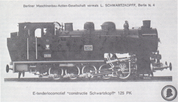
Berliner's official photograph of the first of the Schwartzkopff flexible wheelbase locomotives - their number 8359 of 1924, and PKP 2600. (collection M. Murray)
(Ray Fox has also written in with a description of the Schwartzkopff system, much of his letter duplicating information given above. He further remarks that this could be one of the rarest forms of flexible wheelbase locomotive: Lionel Wiener, in his monumental work "Articulated Locomotives', makes no reference to the Schwartzkopff system! - Hon Eds)
THE DERWENT VALLEY RAILWAY
With reference to this article which appeared in RECORD 51, I should like to inject another name into the confusion over the makers of the early petrol locomotive mentioned on page 134. I suspect that this may have been the demonstration vehicle of the Motorailer Transport Co Ltd, which certainly had some connection with the Four Wheel Drive Company (whose exact title I do not know). There is a report in the "Railway Gazette" of 12th October 1923 (Vol.39, page 468) that this company (of 21, Northumberland Avenue, London WC2) had recently shown a 'Motorailer' at Slough. This was simply a device for fixing rail wheels on to an ordinary lorry, and was shown in use on a FWD vehicle. The precise ownership is, I think, fairly complicated. I believe FWD had premises on the Slough Trading Estate, where this demonstration presumably took place, and in its early days the owners of the Estate (Slough Trading Co Ltd) dealt largely in war surplus vehicles. Was FWD a subsidiary of this Company?
| BROMLEY, KENT |
MICHAEL J. O'CONNOR |
Since this article was published I have found out that CHURCHILL (Fowler 4100005 of 1947) actually belongs to Yorkshire Grain Driers Ltd and not Highlight (Grain Handling) Ltd as quoted on pages 137 and 144 of RECORD 51: there is no connection whatsoever between Yorkshire Grain Driers Ltd and Highlight (Grain Handling) Ltd. Grain supplies appear to be running at a normal level on the railway and, as anticipated, in late 1973 no sugar beet at all was handled. The "BGV's" (Bulk Grain Vehicles) are loaded from a spout by CHURCHILL's driver who therefore has to climb on and off the wagons as required when the train needs moving. He has acquired the art of positioning the wagons under the spout very well - by pacing out the distance from the locomotive and using a stone as a marker!
Work started in December 1973 on clearing and preparing the 10 acre site at Dunnington. The old livestock/sugar beet loading ramp has been removed and access to the site has been made across the railway. Eventually a warehousing area for grain and fertiliser will be provided which could well substantially increase grain traffic on the railway. Sledmere siding, mentioned on page 145, but not detailed on page 138, is actually a short single siding on the north side of the line between Murton Lane and Dunnington stations and forms a trailing connection when travelling towards the latter. It was only ever a beet siding with a high loading platform. At some times in the beet season one of the locomotives was stabled overnight in the siding. Now, with no sugar beet traffic the siding is not needed for this purpose and currently internal rolling stock is stored there. The National Coal Board has announced that the new drift mine to be developed in the Selby area (see page 144) will be rail connected to the BR Leeds- Selby line at Gascoigne Wood (between South Milford and Hambleton) : the DVR will therefore see no additional traffic from this project.
The identity of the Manning Wardle illustrated on page 132 has still not been resolved but I have been told by an elderly BR employee who saw the DVLR being built that a further contractor was involved. Bell's - as he remembers the contractors - did the ballasting for the line and my informant had the job of receiving the incoming ballast trains at Layerthorpe (NER) goods yard. Is it possible that the Manning Wardle was owned by "Bell's"?
Finally, two small typographical errors occurred. On page 131 the maximum number of passengers carried should read 49,983 and on page 142 the opening of Layerthorpe Coal Centre should read 12th October 1964.
| YORK |
R.R. DARSLEY |
Readers may be interested to know of a little-known passenger 'special' which visited this railway on 14th May 1966. The train, organised for a party of BR employees belonging to the British Railways (Eastleigh) Engineering Society, consisted of one BSO coach hauled by BR D2075 and ran from Layerthorpe Station to Wheldrake and back. The coach had been worked round from York (BR) via York yard and Foss Islands by goods train on 12th May.
| EASTLEIGH |
L.F. WHITE |
NARROW GAUGE AT VYRNWY WATERWORKS
I was interested in Mr Higgins' suggestion on page 286 of RECORD 55 that the Talyllyn coach from Boden's Stone Ltd may have been used during the building of the Vyrnwy Waterworks. What a pity the body was destroyed. The coach had been at Boden's since time beyond memory and the thirty years mentioned is a minimum. However, there is no evidence that it came from Lehane, Mackenzie & Shand Ltd; this was put forward as a possibility because they had a depot in the neighbourhood in more recent times. Although the body of the coach at Boden's was scrapped by the Talyllyn Railway, the bogies were regauged and much of the chassis ironwork was re‑used in TR coach No.16. Because the bogies had seen considerable service they were taken to pieces and literally rebuilt, although not altered in design. Four broken axleboxes were renewed to match the originals, and the present brake gear is not like the original. As received at Tywyn, the coach was about 20ft long by 6ft 6in wide, with a body length of 15ft and two end platforms. The body was built of steel sheeting on softwood framing, with end doors to the platforms. Separate hand brakes were fitted to each bogie. The coach had round side buffers and the footsteps were marked "Kerr Stuart & Co., London". The description of the coach offered at Lake Vyrnwy could fit the TR vehicle except that the wheel size is different: TR No.16 has 16in diameter wheels. Also, the design of the bogies is such that they could not have been fitted with 21in diameter wheels as described for the Vyrnwy coach: the existing 16in wheels are obviously the original size. I must acknowledge the assistance of the Chief Engineer of the Talyllyn Railway who has confirmed and supplemented my recollections of the "reservoir" coach.
| NOTTINGHAM |
ANDREW J. WILSON |
![]()
![]()
![]()
![]()