| THE INDUSTRIAL RAILWAY RECORD |
© APRIL 1969 |
![]()
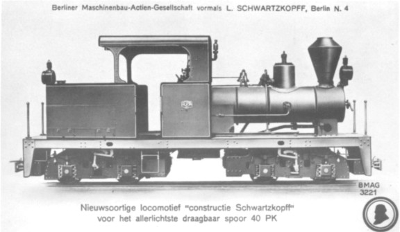
Having enjoyed this article in RECORD 16 I thought the enclosed photograph would be of interest in showing a German builders’ idea of a light articulated locomotive for 700mm gauge. The caption states that it was a "new style of locomotive built by Schwartzkopff for the lightest portable track, 40hp". This particular one had four cylinders 160mm x 230mm and 600mm wheels; the weight was 12˝ tons, and length 7000mm. Unfortunately, no works number is quoted, and I have not been able to trace where it worked. Can any reader help?
| LEEUWARDEN, HOLLAND. |
P. HOOGLAND |
![]()
SWAN VILLAGE GAS WORKS
Through the courtesy of the West Midlands Gas Board some years ago I was able to examine the minute books of the Engineering Sub-Committee of the Gas Committee of Birmingham City Council. The following extracts are of interest and amplify the locomotive details in the article in RECORD 20.
Minute 6109 13/3/82. Application made to West Bromwich Improvement Commissioners to use loco on level crossing at Swan Village. Saving would be Ł162 per annum. Minute 6200 24/4/82. Permission given to use loco across Swan Lane. Tabulated tenders and photographs submitted (not reproduced). Cheapest loco offered by Barr, Morrison and Co., of Kilmarnock for Ł678. Next best offer by Fox Walker and Co, now Thomas Peckett, for Ł725. Recommend acceptance of Peckett offer. Minute 6217 8/5/82. Report on conditions as to crossing Swan Lane embodies "loco not to cross more than 18 times a day; loco not to exceed 3m.p.h." Minute 6248 22/5/82. Mr Peckett granted an additional two weeks to complete loco. Minute 6375 24/7/82. Thomas Peckett has delivered loco to Swan Village. Engine works very well.
Minute 9407 26/9/87. Loco at Swan Village being repaired and horses in use. Second loco at Saltley not available as this is also under repair. Minute 9491 24/10/87. Loco at Swan Village now back at work.
Minute 12286 21/5/91. Loco at Swan Village by Peckett requires overhaul. Three locos at Saltley by Black Hawthorn, two with 10in cylinders and one with 12in. One of smaller ones to be transferred to Swan Village. Minute 123044/6/91. Loco No.1 now transferred to Swan Village. Minute 12414 22/7/91. Transfer of loco No.1 endorsed on boiler insurance. Minute 12506 24/9/91. Tenders received for repair of FORWARD No.3 at Swan Village. Black Hawthorn tender accepted. Minute 12695 10/12/91. FORWARD No.3 returned on 17/10/91.
Engineers Report 20/62 1/4/03. No.22 loco at, Swan Village, supplied by Peckett in 1882, is in bad condition. Suggest a new loco be obtained from W. Bagnall. Minute 22048 2/4/03. Tender from W. G. Bagnall for supply of new loco to Swan Village accepted (Ł750). Minute 22049 2/4/03. Old loco at Swan Village to be advertised for sale and highest offer accepted.
As the Peckett locomotive did not come up to expectations no further orders were received by Peckett from the Birmingham Gas Department for many years. Its shortcomings were still fresh in the minds of both Peckett and the West Midlands Gas Board some seventy years later.
The renumbering of certain locos at Swan Village and Saltley appears to have been in connection with a boiler numbering scheme.
| SOLIHULL, WARWICKSHIRE. |
AIDAN L. F. FULLER |
MINSHALL OF WREXHAM
I note Mr Bates’ remarks regarding T. E. Minshall of Wrexham in RECORD 21, page 308. If from the advertisements it is presumed that Minshall offered the five locomotives for sale it would seem that they had passed to him en bloc. This I very much doubt although it was sometimes the practice of the North London Railway to put the sale of locomotives in Agents’ hands. From my records Nos. 38 - 42 would be disposed of as follows - 2 in 1872,2 in 1873, and 1 in 1874. As Mr Bates points out, these went to industrial concerns and further enquiries confirm this.
| MILL HILL, LONDON NW 7. |
M. J. COX |
MANTON LANE WATERWORKS, BEDFORD
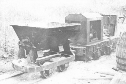
I was interested in this article which appeared in RECORD 20 (page 290). In July 1964 I visited Earls Barton Silica Co Ltd (Northants) where delivery had recently been taken of five wagons and a quantity of rail from, I was told, Bedford Waterworks. I have the impression that this material was actually obtained from W. J. Redden & Sons (scrap merchants of Little Irchester) at the same time as they took away three of Earls Barton’s old locos. The ex−waterworks wagons were unusual in having trunnions at each end so that the bodies could be lifted off by a crane. A U of metal hinged to the upper edge of one end prevented premature tipping, and four steel legs enabled the body to stand upright on the ground. The illustration shows one of these wagons coupled to Orenstein & Koppel diesel loco number 7595.
| KEIGHLEY, YORKS. |
S. A. LELEUX |
(The map on page 359 of RECORD 22 has an error. MILTON EARNEST should read MILTON ERNEST. - Hon Eds)
DOWLAIS IRONWORKS LOCOMOTIVES
The recent acquisition of some photographs of Dowlais locos, which show radical differences from the Pocket Book list, prompt me to ask for the loan of any Dowlais photos that readers may have (particularly a Whitworth set) to enable an article to be written for the RECORD.
| 95 YORK Hill, LOUGHTON, ESSEX. |
FRANK JONES |
STATESIDE SWITCHERS (4) THE HEISLER
I have read RECORD 20 and note your appeal for further information on the lesser known American articulated locomotives. The Shay was, as stated, the most widely used type, indeed this was the most successful articulated locomotive type in the World. (The Mallet is not articulated, but semi-rigid.) The advantages of the Shay over its closest rivals, the Climax and the Heisler, were: -
Engine geometry did not interfere with boiler - especially firebox - design.
Accessibility of mechanical parts was better.
Third and fourth trucks were more easily driven.
Larger locomotives could have three-cylinder engines, thereby improving balance and reducing track damage. The two-cylinder Shay was rather bad in this respect, as the engine side rails suffered by comparison with the boiler side rails.
The Climax, which by the way was more widely used than the Heisler, came in two types. Class A was virtually a motorised boxcar; the boiler was latterly a small locomotive pattern and the engine a two-cylinder vertical unit mounted longitudinally, driving the bogies through cardan shafts and spiral bevel gears. Class B resembled a normal locomotive, having two cylinders mounted normally - at an inclination - driving a crankshaft just ahead of the firebox. This drove the longitudinal shaft by spiral bevels and the drive to the bogies was as previously described. The spiral bevels were a major problem in early days as nobody knew how to generate the tooth form; spiral gears were necessary so that the longitudinal shaft could pass over the nearer axle of each bogie. The advantages of the Climax were simplicity and less track wear.
The Heisler was latterly the only type in which the gears were enclosed, but it never attained the popularity of the other two, probably because of its late appearance. To me the Heisler was the best design mechanically, although for large machines the Shay layout is better.
Dunkirk I do not know, but the few machines produced by Baldwin for logging work were similar to the Shay with the cylinders mounted horizontally under the boiler. This retained the accessibility of the Shay while reducing vertical out-of-balance loads and permitting a centrally-mounted boiler. Few were built, presumably because the Shay was so well established and because logging locomotives were generally one-offs in direct contrast to Baldwin mass-production policy.
These notes may help to amplify some more learned discourse from across the Atlantic the subject is one on which one could write a whole RECORD. There are good type histories available of the Shay and Climax, but as yet none of the Heisler. I have seen a lot written about the success of the Shay, but nobody has yet pointed out the really critical advantages of the type apart from that of accessibility. To my mind the introduction of a balanced three-cylinder engine was the turning point in the history of this type, while the ease with which extra trucks could be added became important at a later date. Not until the superb Pacific Coast Shay appeared did Heisler tackle the problem, and the reason is not hard to find. It was much easier to fit extra units to a Climax, but the limiting factor here was the strength of the bevels between crankshaft and longitudinal shaft.
| KENILWORTH, WARWICKS. |
C. R. WEAVER |
In addition to variations of the two truck model as illustrated on page 289 of RECORD 20, some Heislers had an additional tender whose four wheels were connected to the locomotive’s longitudinal drive-shaft, thus making all twelve wheels on three trucks powered. (Incidentally, Shay even built a 16 wheel, 4 truck monster, with the two trucks under its tender powered.)
| KEIGHLEY, YORKS. |
S. A. LELEUX |
![]()
With regard to this article in RECORD 22 (page 362) the impression is given on line 6 that the Deutz locomotives were more powerful than the Rustons, but in fact they were only 25hp. The Rustons - apart from a handful of early machines - were 40hp or 48hp, and the "Wagonmaster" 96hp as stated. I saw the prototype Bord na Mona "Wagonmaster" in July 1966 awaiting repairs at Derrygreenagh workshops. It has one or two detail differences from the Hunslet production batch, and carries a "Bord na Mona 1961" plate on the bonnet front. There is no running number although it is officially known as "LM 176". It seems a very substantial machine for Bord na Mona to have built themselves - but that is the story.
| TOTTERIDGE, LONDON N.20. |
P. S. EXCELL |
INDUSTRIAL LOCOMOTIVES OVERSEAS (6) ROUMANIA
With reference to this article in RECORD 16 and subsequent correspondence, I am able to add some further observations and to correct an error in my own letter on page 226 of RECORD 18. Firstly, the hydro-electric project near Curtea de Arges is now complete and the line, and with it 764−002, has been removed. The factory at Curtea was not in fact connected to this line which was built specifically for early construction work on the dam. The factory mentioned, Intreprinderea Forestičre, has 764 Class locos 374, 413, 431, 440 and 458 on 760mm gauge and I was informed that there were others at the other end of the line (about 20km long); on the standard gauge there were 376−480 (an 0−4−0 diesel) and 140−113 (a "Pershing" of World War 1 vintage).
My other find was in 1968 at Putua, in the extreme north, where a wood products factory produced one loco - 763−126, a very small and attractive 0−6−0 side tank by Krauss (Linz), 1341 of 1923. There had been another loco but it had gone away. Two feeder lines serve the factory, one being 9km long and the other 13km. (In passing, I saw 0−6−2 side tank 395−005 on the Alba Iulia - Zlatna CFR line).
| EDINBURGH, 12. |
J. G. BALLANTYNE |
HENSCHEL LOCOMOTIVES
I was looking through the Henschel works list recently and noticed the following entries for British agents and contractors. Does any reader have any records, which might indicate where the locos went to, "London" obviously being an office address?
| 17659 - 61 of 1920 | 610mm gauge | 0−6−0T | Dow & Wilson, London |
| 20317 of 1920 | metre gauge | 0−6−0T | Dow & Wilson, London |
| 20862 of c1928 | 600mm gauge | 0−4−0T | Robert Hudson & Sons, London |
| 20867 - 68 of c1928 | 1067mm gauge | 0−4−0T | John Jackson, London |
| RAYLEIGH, ESSEX. |
J. MORLEY |
SOME LONG BOILERED LOCOMOTIVES
Several locomotives listed on page 181 of RECORD 17 and recorded as "long boiler" in the Manning Wardle Locomotive Register would appear not to be of the true "long boiler" type, i.e. with all axles in front of the firebox throatplate. These include nos. 88, 89, 92, 110, 126, 127, 134 and 140 which are understood to have had longer boilers than usual (7ft 9in instead of 7ft 3in as generally used on the 11 in 0−6−0 saddle tanks) but there are no drawings to support this assumption, however; the boiler diameter was 2ft 9in.
Apparently Manning Wardle 72 was the first to have the 7ft 9in barrel, but had cylinders 12in by 19in instead of the more normal 11in by 17in; a standard gauge 0−6−0 saddle tank it was despatched on 18th March 1863 to Tooth & Mort, Sydney, New South Wales. Manning Wardle 111 of 1864 was the first 0−6−0 saddle tank of Class K (12in by 17in cylinders) and this had the 7ft 9in barrel. However, neither of these was a "long boiler" locomotive.
Manning Wardle 183 and 184 as shown on p.181 were of the true "long boiler" design, as also were 118 and 119 of 1864; the latter were North Eastern Railway 0−6−0 saddle tanks 518 and 519, recorded as "Intended for Goathland Incline". Manning Wardle 120 and 121 of 1864.were probably of the "long boiler" type, but there are no drawings among the surviving records to prove it; these were North Eastern Railway tender engines 520 and 521, recorded as "Intended for Castleton & Grosmont Rly".
| HEADINGLEY, LEEDS, 6. |
G. HORSMAN |
RAILS TO THE WELL
I think that the caption to my photograph on page 212 of RECORD 18 is wrong in saying that CLARA was built as a tank engine. After writing the article I’ve seen photographs which showed the Kitson locomotives with tenders shortly after delivery, and I do not think they would have been converted so soon. Incidentally, whilst in India I went to the site of the Cape Copper Company’s mines there. Unfortunately, however, unlike at Nababeeb, no locomotive has been left behind.
| RICHMOND, SURREY. |
FRANK JUX |
![]()
(It seems rather strange that this locomotive, built entirely we presume by the one builder, should have two works numbers - 3486 and T258. One could be excused for thinking that the "T" in T258 could refer to a tender if one had forgotten for instance that Kitson T261 of 1893 was a small 0−4−0 well tank for the Liverpool Overhead Railway. Mr G. Horsman tells us that he understands the Kitson Txxx works numbers apply to Tramway Engines, but no details now survive in the Kitson records held by the Hunslet Engine Company. Kitson allocated blocks of works numbers for Tramway Engines but the individual owners are not recorded, viz 2375-2419, 2541-2580, 2635-2649, 2711-2799, 2906-2950, 3464-3500 and 3620-3640. In the early days Kitson did allocate works numbers for tenders - two goods engines built for the York, Newcastle & Berwick Railway in 1854 had works numbers 368369 (locos) and 370-371 (tenders) - but by the 1890’s this practice had ceased. Six 0−6−0’s built in 1892 for the Hull & Barnsley Railway (H & BR 57-62) carried works numbers 3504-3509, but the tenders were recorded simply as Batch No.54. The Kitson records surviving at Hunslet do not state whether CLARA was tank or tender. Further information on the subject of Kitson works numbers and on CLARA in particular would be most welcome. - Hon. Eds)
LODGE HILL & UPNOR RAILWAY
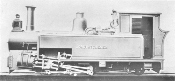
The well-known Yorkshire Engine Company official blocked out photograph of LORD KITCHENER was taken at Chattenden shed. I have a commercial unblocked print made in 1907 showing the carriage shed in the background, with a reference on the back stating "Loco No.2 Lord Kitchener". Clearly the engine was painted a fairly light colour, not black as suggested on page 74 (RECORD 14) and neither is it black in the photograph on page 285 RECORD 12.
| BRIERLEY HILL, STAFFS. |
R. T. RUSSELL |
(Perhaps we should qualify our remarks on page 74 of RECORD 14 with further information extracted from the surviving records of the Yorkshire Engine Company. It is possible that only the lining-out on PIONEER was similar to that on LORD KITCHENER, and whilst it was the intention that PIONEER should be painted black we can find no record of any painting instructions for LORD KITCHENER. Readers can compare the latter’s livery on the official Yorkshire Engine Company photograph reproduced here with that of KITCHENER as illustrated on page 285 of RECORD 12; several structural differences are also apparent, but these were not carried out by the Yorkshire Engine Company as there is no mention in their very complete records.
On page 74, the phrase "improved on in places" was included within quotation marks in error. The remarks following that phrase were in a letter concerning PIONEER from which we are making further quotations below; some other extracts referring to PIONEER from Yorkshire Engine Company records are also included. We find it a little surprising that the modifications to PIONEER should be covered by Order number 17720 and the repairs by 17520, especially when some of the "modifications" in 17720 were shown as "repairs" in 17520! Drawings showing the modifications are not thought to have survived, but the Drawings Register shows that between 30th August 1904 and 24th October 1904 ten additional drawings (including one general arrangement drawing) were commenced for Order 17520. These covered alterations to buffers, front drawgear, steam drum, castings for drum and oil filling hole on tank, whistle pillar and union external steam pipe coupling, double clack box, and some other minor items. Only two new drawings were made for Order 17720; dated 24th February 1905, these showed a longitudinal and a cross section of the cylinder.
(1) Yorkshire Engine Company’s manuscript transcript in "Specification Book No.8" of a letter dated 2nd January 1903 received from Capt Charles H M Nugent, Inspector of Iron Structures at the War Office, and referring to PIONEER.
"I have carefully considered the drawings sent with your letter of the 22nd ultimo, and my remarks thereon are subjoined.
FIREBOX I have no objection to the use of a solid ring for the fire-hole.
FOUNDATION RING I cannot agree to the substitution of a solid ring for the one shewn on my drawings. Your opinion is possibly quite correct on this point, but the engine is an experimental one, and I am anxious to try whether the form I propose will prove useful when the engine has to work with very bad water.
CROWN STAYS Here again it will be preferable to adhere to the drawing sent from this Office. Your arguments have much weight, and no doubt there will be a good deal of trouble in melting up the stays. Still I think it can be managed and should like to see it tried …...... …......
FRAMES In point of strength and stiffness there is an undoubted advantage in the arrangement you show, but the question of minimising the weight is of the first importance and this factor appears to have been lost sight of by you. It is regretted therefore that the modifications submitted cannot be approved. There does (sic) not appear to be any hangers passing through the frame which is of sufficient strength to admit of this motion plate. There is no objection to the casting you suggest.
CROSS STAY The use of studs or bolts will depend upon the arrangement of compensating levers. Bolts will of course now be used.
DRAWINGS Nos. 7 & 8 Your alterations here are distinct improvements and are concurred in. …….. ………
DRAWINGS Nos. 21 & 22 Generally approved, but on further looking into the lateral play of the bogies, 2" on either side appears too little for 100 feet curves, and I shall be glad if you can increase it to 3". The hole in the porter bar should be shaped so as to allow for vertical play in the bogie.
(2) Undated (but in 1904) manuscript entry in "Specification Book No.9". "G.O. 17520 - Specification of Repairs to 2' 6" Loco - War Office." (The specific loco is not mentioned, but the "Further Repairs" specification to the General Order Number indicates it was PIONEER).
"Take the existing dome off the Boiler, add one of greater height, and a steam drum connected by an external pipe to the new dome..... A new dome case is to be provided and also a casing for the drum and the external pipe. The existing mountings and standpipe are to be removed and the former refitted to the drum. In refitting the mountings it is desirable to increase the distances between the handwheels, handles, etc, as some are at present rather awkwardly placed. The feed clack valves below the boiler give trouble by leaking. This is probably due to the horizontal passage being placed at too low a level, so that when the valve attempts to close, the returning water cants the valves. A new clack box will be required. The filling holes on the water and oil tanks will require alteration to suit the external pipe referred to (above). .... Provide new plungers & guides for valve Gear as shewn on drawing 38401. Reduce the lap of valves so as to give lead & alter reversing gear so as to obtain greater travel for the valve. It will probably be found possible to give the die blocks rather more travel in the slot links by shortening one arm of the bell crank lifting lever. The springs controlling the play of the radial pony trucks are too stiff. Lighter ones should be provided and the parts generally require easing. During the trials at Chatham one of the brackets on the bogie frame was broken, and either a new casting must be supplied or a new bracket fitted. The buffers and draw-gear as supplied were found unsuitable, and one set was broken during the trials. New buffers and draw-gear are to be fitted as shewn on Drawing No.38401. A short length of track 2' 6" gauge and having a portion curved to a radius of 100 feet is to be laid down and the Engine thoroughly tested on this."
(3) Manuscript entry dated 11th March 1905 in "Specification Book No.10". "G.O. 17720 Specifications of Modifications to 2' 6" Gauge Loco Supplied against C126." (C126, i.e. Contract 126, covered the construction and sale of PIONEER).
"Providing new steam dome of increased capacity and fitting same to existing seating of boiler. .... Fitting existing safety valves to steam dome. Providing and fitting new casing to steam dome. Providing and fitting new steam drum, also stand pipes and copper connecting pipe between steam drum and dome. .... Water Tank: Removing existing filling hole to position in front of steam dome, covering and making good existing hole in tank, cutting new hole in tank and fitting filling hole mouthpiece to same. Oil Tank: Removing existing filling hole and covering same with plate. Providing new mouthpieces and fitting same to openings in tank for warming coils. .... Cylinders & Valve Gear: Providing and fitting two new cylinders. each of them with new pistons, also back and front cylinder covers. Making the necessary alterations to valves of cylinder. Providing and fitting new valve spindles, guides, bushes &c, .... Draw Gear: Taking down existing draw gear and buffers at each end of Engine. Providing and fixing new cast steel buffers, also new draw gear to Engine. Bogies: Providing and Fixing new cast steel bogie distance piece to replace broken one."
(4) Manuscript entry dated 16th May 1905 in "Specification Book No.10". "G.O. 17520 - Specification of Further Repairs to Loco - War Office".
(The loco is not identified in the heading, but the last sentence below indicates it was PIONEER. These repairs are the "several minor alterations" mentioned on page 74 of RECORD 14; that information was obtained from "Drawing Office Order Book No.12" under date 30th August 1904, Order No.17520).
"Increase clearance between crankpin and crosshead. Alter sandpipes to deliver over rail. Lag steam drum and pipe with asbestos cloth. Add suspension bolt to pony trucks. It is however thought that it would be better to arrange to have this bolt fixed in the truck and have the slot in the under frame of the engine, as it is considered that a slot in the truck will drain the lubricating grooves. Perhaps you will consider this and let me know if you concur. Remedy defect in hanger on left side of trailing bogie. It is proposed to have the engine painted 2 coats black, lined out in red similar to "Lord Kitchener". The name "Pioneer" to be also similarly painted on."
We regret being unable to illustrate PIONEER but no official photograph appears to have been taken. If any reader can provide a picture (or sketch or drawing) we will find space in a subsequent issue. Incidentally our suggestion on page 74 of RECORD 14 that the "minor alterations" might have been carried out at Chattenden now seems doubtful in view of the above. Any further information would be very welcome. - Hon Eds.)
A PRESERVATION QUERY
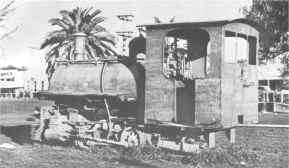
I wonder if you can help me to identify the locomotive shown in this photograph. It was sent to me by the widow of a former pen-friend in New Zealand who knows nothing of the locomotive except that is "preserved" on the front at Wairoa, Hawke’s Bay province, North Island, New Zealand. It appears to be of American build with high couplings, so that presumably at some stage it shunted "main-line" wagons.
| LEICESTER. |
BRUCE D. PALMER |
![]()
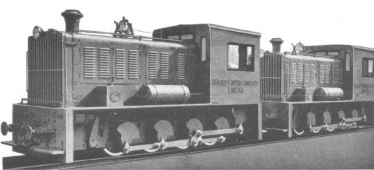
In reading thru this article in RECORD 18 I find I can add a little concerning the O’Okiep Copper Company locos mentioned on page 213. This firm bought two 250hp 2ft 6in gauge 0−8−0 diesel mechanical locos in February 1938 from the Vulcan Iron Works, USA, construction numbers 4237 and 4238. VIW records show them as later sold to the Newmont Mining Corporation which I understand is an American concern (Newmont itself had three 60 cm gauge diesels built post-war by VIW and numbered TSUMEB Nos. 6, 7 and 10.) The enclosed photograph (copied from an official brochure) shows that the O’Okiep running numbers - the same as the VIW construction numbers - are painted on the lower leading corner of the cab, the usual place on VIW locos unless instructions were given otherwise. Notice the solid construction, the steam loco stack (chimney), and the bell.
| NEW YORK, USA. |
HARRY GOLDSMITH |
(David Cole points out that the two 0−8−0’s went to the Tsumeb Mines of the Tsumeb Corporation in South West Africa - presumably Newmont is an associated company. He also gives a list of the 2ft 6in gauge Cape Copper Company steam locos:
| 1 - 3 | 0−4−0T | Kitson | T198, T220 (1886) and T234 (1887) |
| 4 - 5 | 0−6−2T | Kitson | T246/3475 (1890) and T258/3486 (1891) |
| 6 - 7 | 0−6−2T | Kitson | T261/3487 (1892) and T287 (1897) |
| 8 - 10 | 0−6−2T | Kitson | 3976 (1900) and 4089, 4090 (1901) |
| 11 | 0−4−0T | Dick Kerr | (1904) |
| 12 | 0−6−2T | Kitson | 4291 (1904) |
| 13 | 0−4−0T | Dick Kerr | (1905) |
| 14 - 15 | 0−6−2T | Kitson | 4331 and 4332 (1905) |
| 16 - 17 | 0−4−0ST | Bagnall | 1894 (1912) and 2038 (1915) |
The inclusion of Bagnall 1894 and 2038 is interesting for we have always understood (vide page 268 of Pocket Book 6) that these were at the Cape Copper Company’s Jersey Marine Works near Swansea, Glamorgan, along with six similar Bagnall locos (1963, 1978, 2004, 2010, 2039 and 2056). Is there any positive record of delivery of any of these Bagnalls to either Jersey Marine or South West Africa? - Hon Eds.)
![]()