| THE INDUSTRIAL RAILWAY RECORD |
© FEBRUARY 1969 |
TINSLEY VIADUCT, SHEFFIELD
SYDNEY A. LELEUX
While travelling southwards by train on the former Midland Railway main line I noticed, on the north-eastern outskirts of Sheffield, a small green locomotive moving across a massive girder spanning the main line. I saw this locomotive on several subsequent journeys and eventually, on 19th July 1966, I broke my journey to investigate. The locomotive belonged to the Cleveland Bridge & Engineering Co Ltd of Darlington who were constructing a double deck viaduct nearly ľ mile long across the valley of the River Don at Tinsley. On its upper deck, the viaduct was to carry the M1 motorway extension from Sheffield to Leeds with the lower deck providing a link road for local traffic across the valley.
The major problem in building the viaduct was that of access to the site, for the viaduct was to cross numerous railway lines, a canal, the River Don and several factories. Because of this, delivery of materials to the site at ground level was impossible and the method adopted overcame this problem by building the viaduct outwards from the north-western end, components being brought out along the already completed sections. To facilitate the movement of materials along the viaduct, a railway was laid on the lower deck as it was extended.
Fortunately the first few sections of the viaduct spanned the Sheffield to Rotherham line which meant that components could be delivered by rail, direct from the Darlington factory. On my visit, the railway ran along the lower deck for almost its whole length except for a distance of about 50ft from the northern abutment where it ran on to a steel trestle to the north of the bridge. This enabled a crane to lift materials from the British Railways’ sidings directly on to the contractor’s railway.
The principle components of the viaduct were the main longitudinal box girders, each 50 ft. long and weighing 25 tons, which in some cases arrived at the site with the rails for the contractor’s railway already in position on them. These girders were carried out to the erection point on two specially built bogies, which were simple steel trolleys 12ft long and 6ft 6in wide with four double flanged wheels and a single central bolster that could swivel to accommodate curves in the track. Each bogie was designed to carry 15 tons and ran on 5ft 2˝in gauge track. The locomotive though was 3ft gauge, the broader gauge being used in order to ensure stability when moving a load in a high wind; the track therefore was mixed gauge, the outer rail being common to both gauges.
The locomotive, numbered E9, was a Class DSH 48hp diesel built by Ruston & Hornsby Ltd in 1958 (works number 411322) which had arrived at Tinsley in April 1966 from Thos W Ward Ltd. It had formerly worked at the British Railways Beeston Sleeper Depot near Nottingham, where it was numbered ED 10. When the girder sections were bolted together, it was found that the locomotive’s wheel flanges sometimes struck the bolt heads. This was because the rails were not conventional but simple steel bars of small section. There was no danger of derailment when the wheels struck the bolts at low speeds, but it irritated the loco driver who said that, during the annual holidays, the flanges were to be turned down slightly to overcome the difficulty.
When the steel erecting was finished in 1967 the railway ceased work. The rails were covered by the deck concrete, the trestle dismantled and the locomotive taken to the Darlington depot to await work on another contract.
I would like to thank the Cleveland Bridge & Engineering Co Ltd for their help in preparing this article.
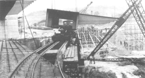
Loading girder section onto bogies. Note mixed gauge track. 19th July 1966. (Author)
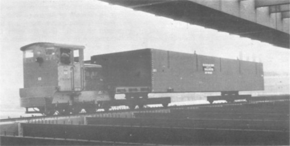
Ruston 411322 propelling a girder section out along the bridge, 19th July 1966. (Author)
![]()
![]()